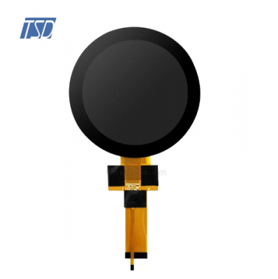
Description:
TST070HDHF-A00 is 7 inch 1280x768 resolution IPS tft lcd module with wide temperate range, support LVDS interface. It's with IPS glass, normally black, transmissive, ADS type. Outline dimension of LCM is 164.06x104.66x6.29mm, active area is 152.45x91.47mm. Standard brightness is 1000 cd/m2. It is a color active matrix thin film transistor liquid crystal display (LCD) that uses amorphous silicon TFT as a switching device. This model is composed of a TFT LCD panel, a driving circuit and a back light system. This TFT LCD has a 7 inch diagonally measured active display area with HD (1280 horizontal by 768 vertical pixel) resolution.
Drawing:


Specifications:
| General Specification | ||
| Part No. | TST070HDHF-A00 | |
| Outline Dimension(mm) | 164.06x104.66x6.29mm |
|
| Active Area(mm) | 152.45x91.47mm | |
| Resolution(dots) | 1280x768 | |
| Operating temperature(°C) | -30 ~ +85°C | |
| Storage temperature(°C) | -40 ~ +90°C | |
| Number of Pixel(pixels) | 1280(H)xRGBx768(V) | |
| Touch panel | without | |
| Brightness | 1000 cd/m2 | |
| Pixel arrangement | RGB-stripe | |
| Display mode | Normal black,IPS, 7 inch TFT | |
| Surface treatment | Antiglare | |
| View direction | All |
|
| Weight(g) | TBD | |
| Power Consumption(w) | Panel | TBD(Typ.) |
| B/L system | TBD(Typ.) | |
| Interface | LVDS | |
| Module lifetime(Hours) | 30,000 | |
| Pins Description | ||
| Pin No. | Symbol | Description |
| 1 | LEDA | LED Anode |
| 2 | LEDA | LED Anode |
| 3 | LEDA | LED Anode |
| 4 | NC | No connection |
| 5 | LEDK | LED Anode |
|
6 |
LEDK | LED Anode |
| 7 | LEDK | LED Anode |
| 8 | I2C_SCL | Serial interface clock input for I2C interface (Please Pull H with 4.7KΩ resistance) |
| 9 | I2C_SDA | Serial Interface address and data input/output for I2C interface (Please Pull H with 4.7KΩ resistance) |
| 10 | OTP | Power input for OTP programming. Leave this pin open or Connect it to VCC when not programming OTP |
| 11 | NTC | Thermistor pin |
| 12 | NTC | Thermistor pin |
| 13 | VCC | Power for Digital Circuit |
| 14 | VCC | Power for Digital Circuit |
| 15 | GND | Power ground |
| 16 | GND | Power ground |
| 17 | Fail_DET | Error feedback |
| 18 | STBYB | Standby mode setting pin. Active low, Timing controller, Output buffer, DAC and power circuit all off when STBYB is low (STBYB must meet the sequence of Driver IC when poweron/off;) |
| 19 | LR | Left/right selection |
| 20 | UD | Up/down selection |
| 21 | GND | Power ground |
| 22 | LVDS_RX_IN3+ | LVDS data lane 3 Positive |
| 23 | LVDS_RX_IN3- | LVDS data lane 3 Negative |
| 24 | GND | Power ground |
| 25 | LVDS_CLK_IN+ | LVDS Clock Lane Positive |
| 26 | LVDS_CLK_IN- | LVDS Clock Lane Negative |
| 27 | GND | Power ground |
| 28 | LVDS_RX_IN2+ | LVDS data lane 2 Positive |
| 29 | LVDS_RX_IN2- | LVDS data lane 2 Negative |
| 30 | GND |
Power ground
|
| 31 | LVDS_RX_IN1+ | LVDS data lane 1 Positive |
| 32 | LVDS_RX_IN1- | LVDS data lane 1 Negative |
| 33 | GND |
Power ground
|
| 34 | LVDS_RX_IN0+ |
LVDS data lane 0 Positive
|
| 35 | LVDS_RX_IN0- | LVDS data lane 0 Negative |
| 36 | GND | Power ground |
| 37 | RESET | Global Reset pin. Active low, If RESETB=0, the chip is in reset state. (RESETB must meet the sequence of Driver IC when power on/off; Add external RC circuit(R=10Kohm, C=1uF) to pin RESETB to start whole chip reset when power up |
| 38 | GND | Power ground |
| 39 | BRS | No connection |
| 40 | GND | Power ground |
Features:
7 (15:9 diagonal) inch configuration
ROHS Compliance & Halogen Free
TFT LCD Monitor
Amusement
Vehicle
 Email : info@tslcd.com
 Tel : +86-755-28225963


